The BASICS
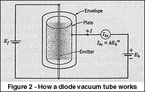
Back in 1904, British scientist John Ambrose Fleming first showed his
device to convert an alternating current signal into direct current. The
"Fleming diode" was based on an effect that Thomas Edison had first
discovered in 1880, and had not put to useful work at the time. This
diode essentially consisted of an incandescent light bulb with an extra
electrode inside. When the bulb's filament is heated white-hot,
electrons are boiled off its surface and into the vacuum inside the
bulb. If the extra electrode (also called an "plate" or "anode") is made
more positive than the hot filament, a direct current flows through the
vacuum. And since the extra electrode is cold and the filament is hot,
this current can only flow from the filament to the electrode, not the
other way. So, AC signals can be converted into DC. Fleming's diode was
first used as a sensitive detector of the weak signals produced by the
new wireless telegraph. Later (and to this day), the diode vacuum tube
was used to convert AC into DC in power supplies for electronic
equipment.
Many other inventors tried to improve the Fleming diode, most without
success. The only one who succeeded was New York inventor Lee de Forest.
In 1907 he patented a bulb with the same contents as the Fleming diode,
except for an added electrode. This "grid" was a bent wire between the
plate and filament. de Forest discovered that if he applied the signal
from the wireless-telegraph antenna to the grid instead of the filament,
he could obtain a much more sensitive detector of the signal. In fact,
the grid was changing ("modulating") the current flowing from the
filament to the plate. This device, the Audion, was the first successful
electronic amplifier. It was the genesis of today's huge electronics
industry.
Between 1907 and the 1960s, a staggering array of different tube
families was developed, most derived from de Forest's invention. With a
very few exceptions, most of the tube types in use today were developed
in the 1950s or 1960s. One obvious exception is the 300B triode, which
was first introduced by Western Electric in 1935. Svetlana's SV300B
version, plus many other brands, continue to be very popular with
audiophiles around the world. Various tubes were developed for radio,
television, RF power, radar, computers, and specialized applications.
The vast majority of these tubes have been replaced by semiconductors,
leaving only a few types in regular manufacture and use. Before we
discuss these remaining applications, let's talk about the structure of
modern tubes.
INSIDE A TUBE
All modern vacuum tubes are based on the concept of the Audion--a heated
"cathode" boils off electrons into a vacuum; they pass through a grid
(or many grids), which control the electron current; the electrons then
strike the anode (plate) and are absorbed. By designing the cathode,
grid(s) and plate properly, the tube will make a small AC signal voltage
into a larger AC voltage, thus amplifying it. (By comparison, today's
transistor makes use of electric fields in a crystal which has been
specially processed--a much less obvious kind of amplifier, though much
more important in today's world.)
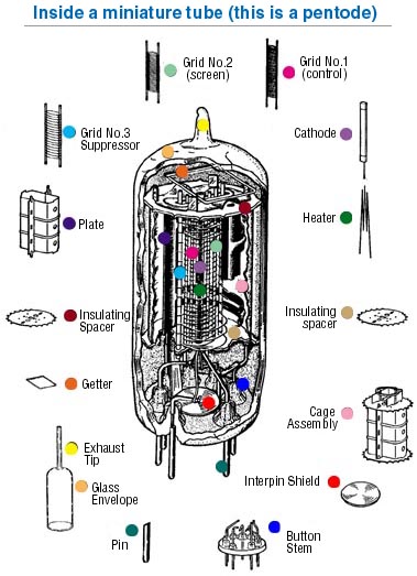
Figure 3 (Inside a miniature tube) shows a typical modern vacuum
tube. It is a glass bulb with wires passing through its bottom, and
connecting to the various electrodes inside. Before the bulb is sealed,
a powerful vacuum pump sucks all the air and gases out. This requires
special pumps which can make very "hard" vacuums. To make a good tube,
the pump must make a vacuum with no more than a millionth of the air
pressure at sea level (one microTorr, in official technical jargon). The
"harder" the vacuum, the better the tube will work and the longer it
will last. Making an extremely hard vacuum in a tube is a lengthy
process, so most modern tubes compromise at a level of vacuum that is
adequate for the tube's application.
First, let's talk about the parts of the tube.........
A. Cathode
Today, nearly all tubes use one of two different kinds of cathode to
generate electrons.
1) The thoriated filament: it is just a tungsten filament, much like
that in a light bulb, except that a tiny amount of the rare metal
THORIUM was added to the tungsten. When the filament is heated white-hot
(about 2400 degrees Celsius), the thorium moves to the outer surface of
it and emits electrons. The filament with thorium is a much better maker
of electrons than the plain tungsten filament by itself. Nearly all big
power tubes used in radio transmitters use thoriated filaments, as do
some glass tubes used in hi-fi amps. The thoriated filament can last a
VERY long time, and is very resistant to high voltages.
2) The other kind of cathode is the oxide-coated cathode or filament.
This can be either just a filament coated with a mixture of barium and
strontium oxides and other substances, or it can be an "indirectly
heated" cathode, which is just a nickel tube with a coating of these
same oxides on its outer surface and a heating filament inside. The
cathode (and oxide coating) is heated orange-hot, not as hot as the
thoriated filament--about 1000 degrees Celsius. These oxides are even
better at making electrons than the thoriated filament. Because the
oxide cathode is so efficient, it is used in nearly all smaller glass
tubes. It can be damaged by very high voltages and bombardment by stray
oxygen ions in the tube, however, so it is rarely used in really big
power tubes.
3) Lifetime of cathodes: The lifetime of a tube is determined by the
lifetime of its cathode emission. And the life of the of a cathode is
dependent on the cathode temperature, the degree of vacuum in the tube,
and purity of the materials in the cathode.
- Tube life is sharply dependent on temperature, which means that it
is dependent on filament or heater operating voltage. Operate the
heater/filament too hot, and the tube will give a shortened life.
Operate it too cool and life may be shortened (especially in thoriated
filaments, which depend on replenishment of thorium by diffusion from
within the filament wire). A few researchers have observed that the
lifetime of an oxide-cathode tube can be greatly increased by
operating its heater at 20% below the rated voltage. This USUALLY has
very little effect on the cathode's electron emission, and might be
worth experimenting with if the user wishes to increase the lifetime
of a small-signal tube. (Low heater voltage is NOT recommended for
power tubes, as the tube may not give the rated power output.)
Operating the heater at a very low voltage has been observed to
linearize some tube types-- we have not been able to verify this, so
it may be another worthy experiment for an OEM or sophisticated
experimenter. The average end-user is advised to use the rated heater
or filament voltage--experimentation is not recommended unless the
user is an experienced technician.
- Oxide cathodes tend to give shorter lifetimes than thoriated
filaments. Purity of materials is a big issue in making long-lived
oxide cathodes--some impurities, such as silicates in the nickel tube,
will cause the cathode to lose emission prematurely and "wear out".
Low-cost tubes of inferior quality often wear out faster than
better-quality tubes of the same type, due to impure cathodes.
- Small-signal tubes almost always use oxide cathodes. Good-quality
tubes of this type, if operated well within their ratings and at the
correct heater voltage, can last 100,000 hours or more.
- The world record for lifetime of a power tube is held by a large
transmitting tetrode with a thoriated filament. It was in service in a
Los Angeles radio station's transmitter for 10 years, for a total of
more than 80,000 hours. When finally taken out of service, it was
still functioning adequately. (The station saved it as a spare.) By
comparison, a typical oxide-cathode glass power tube, such as an EL34,
will last about 1500-2000 hours; and a tube with an oxide-coated
filament, such as an SV300B, will last about 4000-10,000 hours. This
is dependent on all the factors listed above, so different customers
will observe different lifetimes.
B. Plate (anode)
The plate, or anode, is the electrode that the output signal appears
on. Because the plate has to accept the electron flow, it can get hot.
Especially in power tubes. So it is specially designed to cool itself
off, either by radiating heat through the glass envelope (if it's a
glass tube), or by forced-air or liquid cooling (in bigger metal-ceramic
tubes). Some tubes use a plate made of graphite, because it tolerates
high temperatures and because it emits very few secondary electrons,
which can overheat the tube's grid and cause failure. See "H--the
getter" below for more about the graphite plate.
C. Control Grid
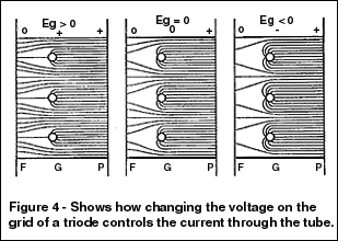
In nearly all glass audio tubes, the control grid is a piece of
plated wire, wound around two soft-metal posts. In small tubes the
plating is usually gold, and there are two posts made of soft copper.
Grids in big power tubes have to tolerate a lot of heat, so they are
often made of tungsten or molybdenum wire welded into a basket form.
Some large power tubes use basket-shaped grids made of graphite (see D
below).
Inside any modern amplifying tube, one of the things to avoid is
called secondary emission. This is caused by electrons striking a smooth
metal surface. If many secondary electrons come out of the grid, it will
lose control of the electron stream, so that the current "runs away",
and the tube destroys itself. So, the grid is often plated with a metal
that is less prone to secondary emission, such as gold. Special surface
finishing is also used to help prevent secondary emission.
A tube with only one grid is a TRIODE. The most widely used small
triode, the 12AX7, is a dual triode which has become the standard
small-signal amplifier in guitar amps. Other small glass triodes used in
audio equipment include the 6N1P, 6DJ8/6922, 12AT7, 12AU7, 6CG7, 12BH7,
6SN7 and 6SL7.
Many glass power triodes are currently on the market, most of them
aimed at amateur radio or high-end audio use. Typical examples are the
Svetlana SV300B, SV811/572 series, and 572B. Power triodes come in
"low-mu" (low gain) and "high-mu" (high gain) versions. Low-mu triodes
like the SV300B have very low distortion and are used in high-end audio
amplifiers, while high-mu triodes are used mostly in radio transmitters
and big high-power audio amplifiers.
Large ceramic-metal power triodes are often used in radio
transmitters and to generate radio energy for industrial heating
applications. Specialized triodes of many kinds are made for exotic
applications, such as pulsed radars and high-energy physics work.
D. Screen grid--the tetrode
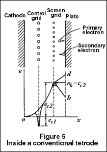
Adding another grid to a triode, between the control grid and the
plate, makes it into a TETRODE. This "screen" grid helps screen, or
isolate, the control grid from the plate. This is important is reducing
the so-called Miller effect, which makes the capacitance between the
grid and plate look much bigger than it really is. The screen also
causes an electron-accelerating effect, increasing the tube's gain
dramatically. The screen grid in a power tube carries some current,
which causes it to heat up. For this reason, screen grids are usually
coated with graphite, to reduce secondary emission and help keep the
control grid cool.
Many large radio and TV stations use giant metal-ceramic power
tetrodes, which are capable of high efficiency when used as RF power
amplifiers. Power tetrodes are also sometimes used in amateur radio and
industrial applications. (Regular tetrodes are rarely used for audio
applications because of an effect called "tetrode kink", caused by that
secondary emission. Most of it is due to electrons bouncing off the
plate, some from the screen.) This greatly increases distortion and can
cause instability if not carefully dealt with in the design. See section
F, "audio beam tetrodes", below.)
Large ceramic tetrodes are often called "radial beam tetrodes" or
simply "beam tetrodes", because their electron emission forms a
disc-shaped beam. The wires on their control and screen grids are
aligned, a special trick which improves efficiency.
E. Other grids--the pentode
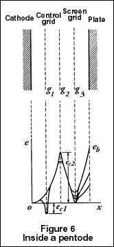
By adding a third grid to the tetrode, we get a PENTODE. The third
grid is called a suppressor grid and is inserted between the plate and
the screen grid. It has very few wire turns, since its only job is to
collect the stray secondary-emission electrons that bounce off the
plate, and thereby eliminate the "tetrode kink". It is usually operated
at the same voltage as the cathode. Tetrodes and pentodes tend to have
higher distortion than triodes, unless special circuit designs are used
(see ULTRALINEAR, below).
The EL34, EL84, SV83 and EF86 are true pentodes. The EL34 is widely
used in guitar and high-end amplifiers as the power output tube. The
smaller EL84 is seen in lower-cost guitar amps. The SV83 is used in a
few high-end and guitar amps, while the EF86 is used as a low-noise
preamp in guitar amps and professional audio equipment. One of the few
large high-power pentodes is the 5CX1500B, often seen in radio
transmitters.
There were tubes with more than three grids. The pentagrid converter
tube, which had five grids, was widely used as the front-end frequency
converter in radio receivers. Such tubes are no longer in production,
having been fully replaced by semiconductors.
F. Audio Beam Tetrode
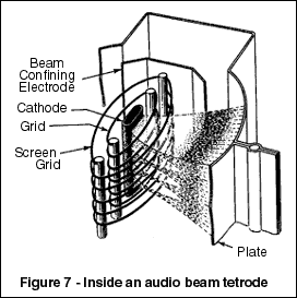 This
is a special kind of beam tetrode, with a pair of "beam plates" to
constrain the electron beam to a narrow ribbon on either side of the
cathode. Also, the control and screen grids have their wire turns
aligned, much like the large ceramic tetrodes (above). Unlike the
ceramic tetrodes, the grids are at a critical distance from the cathode,
producing a "virtual cathode" effect. All this adds up to greater
efficiency and lower distortion than a regular tetrode or pentode. The
first popular beam tetrode was the RCA 6L6, introduced in 1936. Beam
tetrodes still made today include the SV6L6GC and SV6550C; the former is
most popular in guitar amplifiers, while the latter is the most common
power tube in modern high-end audio amplifiers for the home. Today this
design is seen only in glass tubes used in audio amplifiers, not in
ceramic power tubes. This
is a special kind of beam tetrode, with a pair of "beam plates" to
constrain the electron beam to a narrow ribbon on either side of the
cathode. Also, the control and screen grids have their wire turns
aligned, much like the large ceramic tetrodes (above). Unlike the
ceramic tetrodes, the grids are at a critical distance from the cathode,
producing a "virtual cathode" effect. All this adds up to greater
efficiency and lower distortion than a regular tetrode or pentode. The
first popular beam tetrode was the RCA 6L6, introduced in 1936. Beam
tetrodes still made today include the SV6L6GC and SV6550C; the former is
most popular in guitar amplifiers, while the latter is the most common
power tube in modern high-end audio amplifiers for the home. Today this
design is seen only in glass tubes used in audio amplifiers, not in
ceramic power tubes.
G. The heater inside the cathode
An oxide-coated cathode can't heat itself, and it has to be hot to
emit electrons. So, a wire filament heater is inserted within the
cathode. This heater has to be coated with an electrical insulation that
won't burn up at the high temperatures, so it is coated with powdered
aluminum oxide. This is an occasional cause of failure in such tubes;
the coating rubs off or cracks, so the heater can touch the cathode.
This can prevent normal operation of the tube. And if the heater is
running from AC power, it can put some of the AC signal into the
amplifier's output, making it unusable in some applications.
Good-quality tubes have very rugged and reliable heater coatings.
H. The getter
We want a good, hard vacuum inside a tube, or it will not work
properly. And we want that vacuum to last as long as possible.
Sometimes, very small leaks can appear in a tube envelope (often around
the electrical connections in the bottom). Or, the tube may not have
been fully "degassed" on the vacuum pump at the factory, so there may be
some stray air inside. The "getter" is designed to remove some stray
gas.
The getter in most glass tubes is a small cup or holder, containing a
bit of a metal that reacts with oxygen strongly and absorbs it. (In most
modern glass tubes, the getter metal is barium, which oxidizes VERY
easily when it is pure.) When the tube is pumped out and sealed, the
last step in processing is to "fire" the getter, producing a "getter
flash" inside the tube envelope. That is the silvery patch you see on
the inside of a glass tube. It is a guarantee that the tube has good
vacuum. If the seal on the tube fails, the getter flash will turn white
(because it turns into barium oxide).
There have been rumors that dark spots on getters indicate a tube
which is used. This is NOT TRUE. Sometimes, the getter flash is not
perfectly uniform, and a discolored or clear spot can occur. The tube is
still good and will give full lifetime. THE ONLY RELIABLE WAY TO
DETERMINE THE HEALTH OF A TUBE IS TO TEST IT ELECTRICALLY.
Glass power tubes often do not have flashed getters. Instead, they
use a metal getter device, usually coated with zirconium or titanium
which has been purified to allow oxidation. These getters work best when
the tube is very hot, which is how such tubes are designed to be used.
The Svetlana 812A and SV811 use such getters.
The most powerful glass tubes have graphite plates. Graphite is
heat-resistant (in fact, it can operate with a dull red glow for a long
time without failing). Graphite is not prone to secondary emission, as
noted above. And, the hot graphite plate will tend to react with, and
absorb, any free oxygen in the tube. The Svetlana SV572 series and 572B
use graphite plates coated with purified titanium, a combination which
gives excellent gettering action. A graphite plate is much more
expensive to make than a metal plate of the same size, so it is only
used when maximum power capability is needed. Large ceramic tubes use
zirconium getters. Since you can't see a "flash" with such tubes, the
state of the tube's vacuum has to be determined by electrical means
(sometimes by metering the grid current).
I. Assembling the tube
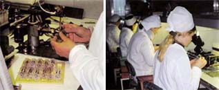
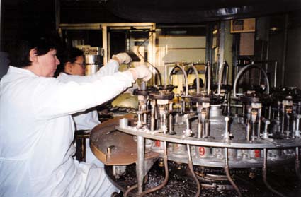
A typical glass audio tube is made on an assembly line by people
wielding tweezers and small electric spot-welders. They assemble the
plate, cathode, grids and other parts inside a set of mica or ceramic
spacers, then crimp the whole assembly together. The electrical
connections are then spot-welded to the tube's base wiring. This work
has to be done in fairly clean conditions, although not as extreme as
the "clean rooms" used to make semiconductors. Smocks and caps are worn,
and each workstation is equipped with a constant source of filtered
airflow to keep dust away from the tube parts.
Once the finished assembly is attached to the base, the glass
envelope can be slid over the assembly and flame-sealed to the base
disc. A small glass exhaust tube is still attached, and enters the
envelope. The tube assembly is attached to a processing machine
(sometimes called a "sealex" machine, an old American brandname for this
kind of device). The exhaust tubing goes to a multistage high-vacuum
pump. The sealex has a rotating turntable with several tubes, all
undergoing a different step in the process.
- First comes vacuum pumping; while the pump runs, an RF induction
coil is placed over the tube assembly and all the metal parts are
heated. This helps remove stray gases trapped in the parts, and also
activates the cathode coating.
- After 30 minutes or more (depending on the tube type and the
vacuum desired), the tube is automatically lifted up and a small flame
seals its exhaust tubing.
- The turntable rotates, and there may follow an electrical
"break-in" period where the tube is put through a series of
operational stresses, such as higher-than-rated heater voltages.
- Then the tube is rotated to the getter-flash station, where a
combination of RF induction heating and/or high-voltage discharge
flashes the barium getter.
- Finally the tube is removed, the base wiring is attached to the
external base (if it is an octal base type) with a special
heat-resistant cement, and the finished tube is ready for aging in a
burn-in rack. If the tube meets a set of operational specs in a
special tester, it is marked and shipped.
J. Metal-ceramic power grid types:
If you want to control a LOT of power, a fragile glass tube is more
difficult to use. So, really big tubes today are made entirely of
ceramic insulators and metal electrodes. Otherwise, they are much the
same inside as small glass tubes--a hot cathode, a grid or grids, and a
plate, with a vacuum in-between.
In these big tubes, the plate is also part of the tube's outer
envelope. Since the plate carries the full tube current and has to
dissipate a lot of heat, it is made with either a heat radiator through
which lots of cooling air is blown, or it has a jacket through which
water or some other liquid is pumped to cool it. The air-cooled tubes
are often used in radio transmitters, while the liquid-cooled tubes are
used to make radio energy for heating things in heavy industrial
equipment. Such tubes are used as "RF induction heaters", to make all
kinds of products--even other tubes.
Ceramic tubes are made with different equipment than glass tubes,
although the processes are similar. The exhaust tubing is soft metal
rather than glass, and it is usually swaged shut with a hydraulic press.
All the equipment for exhausting and conditioning the tube is much
larger, since there is more volume to exhaust, and the large metal parts
require more aggressive induction heating. The ceramic parts are usually
ring-shaped and have metal seals brazed to their edges; these are
attached to their mating metal parts by welding or brazing.
WHY ARE TUBES STILL USED?
A. High-end audio
At its low point in the early 1970s, the sales of tube hi-fi
equipment were barely detectable against the bulk of the
consumer-electronics boom. Yet even in spite of the closure of American
and European tube factories thereafter, since 1985 the sales of
"high-end" audio components have boomed. And right along with them have
boomed the sales of vacuum-tube audio equipment for home use. The use of
tubes in this regime has been very controversial in engineering circles,
yet the demand for tube hi-fi equipment continues to grow.
B. Guitar amps
In general, only very low-cost guitar amplifiers (and a few
specialized professional models) are predominantly solid-state. We have
estimated that at least 80% of the market for high-ticket guitar amps
insists on all-tube or hybrid models. Especially popular with serious
professional musicians are modern versions of classic Fender, Marshall
and Vox models from the 1950s and 1960s. This business is thought to
represent at least $100 million worldwide as of 1997.
Why tube amplifiers? It's the tone that musicians want. The amplifier
and speaker become part of the musical instrument. The peculiar
distortion and speaker-damping characteristics of a beam-tetrode or
pentode amp, with an output transformer to match the speaker load, is
unique and difficult to simulate with solid-state devices, unless very
complex topologies or a digital signal processor are used. These methods
apparently have not been successful; professional guitarists keep
returning to tube amplifiers.
Even the wildest rock musicians seem to be very conservative about
the actual equipment they use to make their music. And their preferences
keep specifying the proven technology of vacuum tubes.
C. Professional audio
The recording studio is somewhat influenced by the prevalence of tube
guitar amps in the hands of musicians. Also, classic condenser
microphones, microphone preamplifiers, limiters, equalizers and other
devices have become valuable collectibles, as various recording
engineers discover the value of tube equipment in obtaining special
sound effects. The result has been huge growth in the sales and
advertising of tube- equipped audio processors for recording use.
Although still a minor movement within the multi-billion-dollar
recording industry, tubed recording-studio equipment probably enjoys
double-digit sales growth today.
D. High-power RF applications
Many big radio stations continue to use big power tubes, especially
for power levels above 10,000 watts and for frequencies above 50 MHz.
High-power UHF TV stations and large FM broadcast stations are almost
exclusively powered by tubes. The reason is cost and efficiency--only at
low frequencies are transistors more efficient and less expensive than
tubes.
Making a big solid-state transmitter requires wiring hundreds or
thousands of power transistors in parallel in groups of 4 or 5 at a
time, then mixing their power outputs together in a cascade of combiner
transformers. Plus, they require large heat-sinks to keep them cool. An
equivalent tube transmitter can use only one tube, requires no combiner
(which wastes some power), and can be cooled with forced air or water,
thus making it smaller than the solid-state transmitter.
This equation becomes even more pronounced at microwave frequencies.
Nearly all commercial communication satellites use a traveling-wave tube
for their "downlink" power amplifiers. The "uplink" ground stations also
use TWTs. And for high power outputs, the tube seems to reign
unchallenged. Exotic transistors still are used only for small-signal
amplification and for power outputs of less than 40 watts, even after
considerable advances in the technology. The low cost of RF power
generated by tubes has kept them economically viable, in the face of
advancing science.
USING TUBES
A. Bias
Bias is a negative voltage applied to a power tube's control grid, to
set the amount of idle current the tube draws. It is important to bias a
tube to stay within its rated dissipation. Otherwise, you DO NOT need to
worry about small deviances from the manufacturer's recommendations.
Many times we have customers asking us things like, "I replaced the
tubes, the old tubes ran at 35 mA, the new ones run at 38 mA. I'm
worried that I have to re-bias the amp." This is NOT worth worrying
about. Especially with guitar amps--they tend to run their tubes at idle
conditions which are conservative. Some high-end audio amps run their
power tubes quite hard--in that case, re-biasing is necessary. Many amps
have no bias adjustments at all, and are designed so that you do not
need to concern yourself with bias. This includes most Mesa-Boogie
guitar amps, most amps using EL84s, and many single-ended triode hi-fi
amps. We suggest that users consult with the equipment manufacturer, if
possible.
B. When should I replace the tubes?
Practically speaking, you should only replace tubes in an audio
amplifier when you start to notice changes in the sound quality. Usually
the tone will become "dull", and transients will seem to be blunted.
Also, the gain of the amplifier will decrease noticeably. This is
usually enough of a warning for tube replacement. If the user has very
stringent requirements for observing tube weakening, the best way to
check tubes is with a proper mutual- conductance-style tube tester.
These are still available on the used market; though new ones have not
been manufactured in many years. One tester is being manufactured today,
the Maxi-Matcher. It is suitable for testing 6L6, EL34, 6550 and EL84
types. If you cannot get your own tube tester, speak to a service
technician for his recommendations.
Large ceramic power tubes are usually operated in equipment that has
metering of the plate current or power output. When the tube cannot
reach the rated plate current or power output for the equipment, the
tube is usually considered to be at the end of its normal life. The
operating manual should give a more complete procedure for estimating
the health of the tube.
C. Blue Glow -- what causes it?
Glass tubes have visible glow inside them. Most audio types use
oxide-coated cathodes, which glow a cheery warm orange color. And
thoriated-filament tubes, such as the SV811 and SV572 triodes, show both
a white-hot glow from their filaments and (in some amplifiers) a slight
orange glow from their plates. All of these are normal effects.
Some newcomers to the tube-audio world have also noticed that some of
their tubes emit a bluish-colored glow. There are TWO causes for this
glow in audio power tubes; one of them is normal and harmless, the other
occurs only in a bad audio tube.
- 1) Most Svetlana glass power tubes show FLUORESCENCE GLOW.
This is a very deep blue color. It can appear wherever the electrons
from the cathode can strike a solid object. It is caused by minor
impurities, such as cobalt, in the object. The fast-moving electrons
strike the impurity molecules, excite them, and produce photons of
light of a characteristic color. This is usually observed on the
interior of the plate, on the surface of the mica spacers, or on the
inside of the glass envelope. THIS GLOW IS HARMLESS. It is normal and
does not indicate a tube failure. Enjoy it. Many people feel it
improves the appearance of the tube while in operation.
- 2) Occasionally a tube will develop a small leak. When air gets
into the tube, AND when the high plate voltage is applied, the air
molecules can ionize. The glow of ionized air is quite different from
the fluorescence glow above--ionized air is a strong purple color,
almost pink. This color usually appears INSIDE the plate of the tube
(though not always). It does not cling to surfaces, like fluorescence,
but appears in the spaces BETWEEN elements. A tube showing this glow
should be replaced right away, since the gas can cause the plate
current to run away and (possibly) damage the amplifier.
PLEASE NOTE: some older hi-fi and guitar amplifiers, and a very few
modern amplifiers, use special tubes that DEPEND on ionized gas for
their normal operation.
- -Some amps use mercury vapor rectifiers, such as types 83, 816,
866 or 872. These tubes glow a strong blue-purple color in normal use.
They turn AC power into DC to run the other tubes.
-And occasionally, vintage and modern amplifiers use gas-discharge
regulator tubes, such as types 0A2, 0B2, 0C2, 0A3, 0B3, 0C3 or 0D3.
These tubes rely on ionized gas to control a voltage tightly, and
normally glow either blue-purple or pink when in normal operation. If
you are unsure if these special tubes are used in your amplifier,
consult with an experienced technician before replacing them.
ALSO NOTE: these light sources cannot be seen in metal-ceramic tubes,
because their parts are opaque. As we said above, it is difficult to
tell if a ceramic tube has become gassy. Usually, in a large radio
transmitter, a gassy tube will arc over internally. (This does not
damage the transmitter. It has protective circuits.) The equipment
operating manual should give more information on this.
D. What is Class A, B, AB, ULTRALINEAR,
etc?
1. Class A means that the power tube conducts the same amount of
current all the time, whether idling or producing full power. Class A is
very inefficient with electricity but usually gives very low distortion.
- There are single-ended class-A, or SE, amplifiers. They use one
or more tubes in parallel, which are all in phase with each other.
This is commonly used in smaller guitar amps and in exotic high-end
amplifiers. Many audiophiles prefer the SE amplifier, even though it
has relatively high levels of even-order distortion. Most 300B
high-end amplifiers are SE. Negative feedback, which can be used to
decrease the distortion of an amplifier, is felt by some people to
sound inferior. Most SE amps have no feedback.
- Push-pull class-A amplifiers also exist--they use two, four or
more tubes (always in pairs) which are driven in opposite phase to
each other. This cancels out the even-order distortion and gives very
clean sound. An example of a class-A push-pull amplifier is the Vox
AC-30 guitar amp. Push-pull Class A operation usually involves low
plate voltages and high plate currents, compared to Class AB operation
below. The high currents might tend to wear out the tube cathodes
faster than in an AB amplifier.
- There are two kinds of class-A operation, which can apply to
single-ended or push-pull.
--Class A1 means that the grid voltage is always more negative
than the cathode voltage. This gives the greatest possible linearity and
is used with triodes such as the SV300B, and with audio beam tetrodes
and pentodes.
--Class A2 means that the grid is driven MORE POSITIVE than the
cathode for part or all of the waveform. This means the grid will draw
current from the cathode and heat up. A2 is not often used with beam
tetrodes, pentodes or triodes like the SV300B, especially in audio.
Usually a class-A2 amplifier will use tubes with special rugged grids,
such as the SV811 and SV572 series of triodes.
Class A2 also requires a special driver circuit, that can supply power
to the grid.
2. Class AB applies only to push-pull amplifiers. It
means that when one tube's grid is driven until its plate current cuts
off (stops) completely, the other tube takes over and handles the power
output. This gives greater efficiency than Class A. It also results in
increased distortion, unless the amplifier is carefully designed and
uses some negative feedback. There are class-AB1 and class-AB2
amplifiers; the differences are the same as were explained above--the
tube's grids are not (AB1) or are (AB2) driven positive.
3. Class B applies only to push-pull amplifiers in
audio; it SOMETIMES applies to RF power amplifiers with one tube. It is
like Class AB, except that the tubes idle at or near zero current. This
gives even greater efficiency than Class A or AB. It also results in
increased distortion, unless the amplifier is carefully designed and
uses some negative feedback. If careful design is not undertaken, the
result may be crossover distortion, which appears at the midpoint of the
output waveform and has very bad-sounding effects in audio. Most
solid-state audio amplifiers use class B, because the transistors
undergo less heat stress when idling.
4. ULTRALINEAR operation was invented by David Hafler and
Herbert Keroes in 1951. It uses only beam tetrodes or pentodes, and
special taps on the output transformer. The taps connect to the screen
grids of the tubes, causing the screens to be driven with part of the
output signal. This lowers distortion considerably. It is usually seen
only in hi-fi amplifiers that use power tubes such as the SV6L6GC,
SV6550C, EL84 or EL34.
E. Why are different kinds of power
supplies used in various tube amplifiers? Why do some use tube
amplifiers? Why do some use tube rectifiers, while others use
solid-state rectifiers, while still others have electronic regulation?
Tube rectifiers are still used in power supplies of some guitar amps,
because the current a tube rectifier can produce varies somewhat with
the load. It is quite different in response from a solid-state
rectifier. Many audiophiles also prefer this classic design for much the
same reasons. Also, inexpensive solid-state rectifiers can put "hash"
into a power supply, because of their slow transient capability while
charging and recharging a filter capacitor 50/60 times a second. Special
high-speed silicon rectifiers are available at high cost. They are
rarely used in products other than a few high-end amplifiers. Tube
rectifiers have faster transient response than most solid-state
rectifiers, also making them useful in some high-end designs.
Regulated DC plate power can be very helpful in a push-pull Class AB
amplifier. Because the amp draws greatly different current when at idle
and when delivering full power, a regulated supply "sags" less at full
power, producing better transient response in the amplifier. It is
expensive to regulate the high voltages in a tube amplifier, so it is
done only in expensive top-line models. Class A amplifiers have less
need for regulation since they draw nearly the same DC power at all
times. It is dependent on the circuit design. The only way to see if you
need an amplifier with a regulated supply is to listen to it and
carefully compare it with similar amps with unregulated supplies.
Regulation is almost never used in guitar amps, since the DC power "sag"
causes some signal compression, which is considered part of the desired
sound effect inherent to a guitar amp.
F. What are the advantages of an OTL
amplifier over a conventional one with an output transformer? Should I
get an OTL? What about its reliability issues?
OTL, or output-transformerless, amplifiers are special high-end
products. Because it is expensive and difficult to wind an output
transformer for a tube amplifier to achieve the best possible
performance, some designers have chosen to eliminate the transformer
altogether. Unfortunately, tubes have relatively high output impedances
compared to transistors. So, tubes with large cathodes and high peak
emission capability are used---in many push-pull pairs. A well-designed
OTL is capable of the best audio performance available today. OTLs
usually require more maintenance and greater care in use than
transformer-coupled amps. In recent years, OTLs have gotten a bad
reputation for unreliability. This was only a problem with some low-cost
manufacturers, who have since gone out of business. A well-designed OTL
can be just as reliable as a transformer-coupled amp.
G. There's all this talk about "parallel
feed", "shunt feed", SRPP, "mu followers", and the like. Which should I
use? What's the difference?
Parallel feed and shunt feed are the same technique. Basically, a
choke is used to load the power tube (usually one, in SE mode), while
the output transformer is coupled to the plate of the tube through a
capacitor. So, the plate current of the tube does not flow through the
output transformer. This can be a very expensive technique to implement,
since the choke must be as carefully wound as the output transformer. It
does offer a possible performance improvement. You should try to
audition a parallel-feed high-end amp before buying it. This technique
is considered too expensive for use in guitar amps.
SRPP circuits and mu-follower circuits are special designs which use
a lower tube (for gain), and an upper tube which serves as the plate
load for the lower tube. The upper tube also acts as both a cathode
follower and as a constant-current source for the lower tube. If
properly designed, either circuit can offer improved performance over an
ordinary resistor-loaded tube stage. These circuits are used only in
preamp stages and in the driver stages of power amps, usually SE types,
in high-end audio.
|
|